Logic Circuits – JSS3 Computer Studies Lesson Note (Second Term)
Download Lesson NoteLesson note at a glance
- Subject
- Computer Studies
- Class
- JSS3
- Term
- Second Term
- Topic
- Logic Circuits
- Order
- Topic 4 of 5 this term
- Reading time
- 3 min

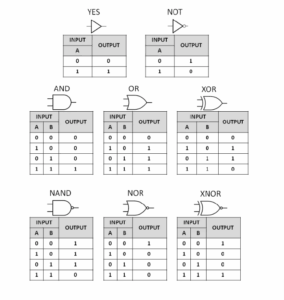
A logic gate is an elementary building block of a digital circuit. Most logic gates have two inputs and one output. At any given moment, every terminal is in one of the two binary conditions low (0) or high (1), represented by different voltage levels. The logic gate’s operation is that it changes, depending on the circuit processes, the inputs’ state. In most logic gates, the low state is approximately 0V, and the high state is approximately 5V, though other ranges may also be used. There are seven basic logic gates: AND, OR, XOR, NOT, NAND, NOR, and XNOR.
And gate
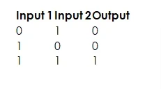
The AND gate is so named because, if it is called “AND,” it is called “True,” the gate acts in the same way as the logical word “AND.” The following illustration and table show the AND gate’s standard logic combinations for a two-input gate. In other words, the gate examines its two inputs, and if both inputs are 1 (high), the output is “True” when both inputs are “True.” Otherwise, the output is “False.”
Or gate
The OR gate gets its name from the fact that it behaves after the fashion of the logical inclusive “OR.” The output is “True” if either or both of the inputs are “True.” If both inputs are “False,” then the output is “False.”

Xor gate
The XOR (exclusive-OR) gate acts in the same way as the logical “either/or.” The output is “True” if either but not both of its inputs are “True.” The XOR gate’s output is “True” if one of its inputs is “True” or both inputs are “False.” However, when both inputs are 1 (high), the output is False. The Boolean equation for XOR is A⊕B = (A·B’) + (A’·B).,

Inverter or not gate
An inverter, sometimes called a NOT gate, is used to differentiate it from other types of electronic gates. It has only one input and inverts its logic state.

Nand gate
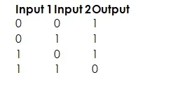
The NAND gate operates as an AND gate followed by a NOT gate. It acts in the reverse of the logical operation “AND” followed by inversion. The output is “False” if both inputs are “True.” Otherwise, the output is “True.”
Nor gate
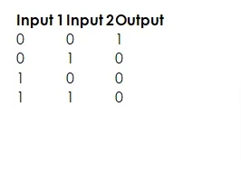
The NOR gate is a combination OR gate followed by an inverter. Its output is “True” if both inputs are “False.” Otherwise, the output is “False.”
Xnor gate
The XNOR gate is a combination inverter / NOT gate followed by an XOR gate. Its output is “True” if both inputs are “False.” Otherwise, the output is “False.”
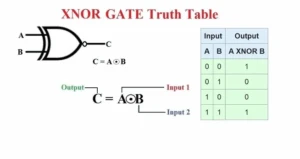
Using a combination of logic gates, complex operations can be performed. In theory, there is no limitation to the number of gates that can be arranged together in a single device. But in practice, there is a limit on the number of gates that can be packed into a given physical space. Arrays of logic gates are found in digital integrated circuits (ICs). For laboratory observation, the reversed input values for each individual logic gate decrease, and digital devices of the same or similar type become capable of performing more complicated operations at ever-increasing speeds.
Uses of Standard Logic Circuits:
- Logic gates are building blocks of hardware electronic components.
- It is used in the education of circuits.
- The AND gate is used to create a multiple signal.
- The NOT gate is used in building a switch.
EVALUATION
State the uses of standard logic circuits.
This term's Computer Studies topics
JSS3 Second Term · 5 topics
- Graphs
- Editing Graphs
- Computer Professionals
- Logic Circuits
- Computer Games
Second Term Computer Studies Lesson Notes for Other Topics

Starting Up a Computer
Read the full lesson note.

Parts of a Computer (Peripherals)
Read the full lesson note.

Starting Up a Computer
Read the full lesson note.
Basic Safety for Computers
Read the full lesson note.
Computer Room
Read the full lesson note.

Computer Room
Read the full lesson note.
Basic Safety for Computer Room
Read the full lesson note.
System Application
Read the full lesson note.
Important Computer Applications
Read the full lesson note.

Difference Between Hardware And Software
Read the full lesson note.
Components Of CPU
Read the full lesson note.

More Parts Of The CPU
Read the full lesson note.
Arithmetic Logic Unit (ALU) & Storage Unit in CPU
Read the full lesson note.
Input Devices
Read the full lesson note.

Launching Microsoft Word
Read the full lesson note.
Lesson Notes for Other Classes

Basic 1 Lesson Note
The complete lesson note to guide your studies.
Basic 2 Lesson Note
The complete lesson note to guide your studies.

Basic 3 Lesson Note
The complete lesson note to guide your studies.

Basic 4 Lesson Note
The complete lesson note to guide your studies.

Basic 5 Lesson Note
The complete lesson note to guide your studies.

Basic 6 Lesson Note
The complete lesson note to guide your studies.