
Simple AC Circuit – SS3 Physics Lesson Note (Second Term)
Lesson note at a glance
- Class
- SS3
- Subject
- Physics
- Term
- Second Term
- Reading time
- 9 min
An alternating current (AC) circuit is a circuit in which the voltage and current change direction regularly, with the voltage varying as V = Vo sin ωt.
Behavioural objectives
By the end of the lesson, students should be able to:
- State how the voltage in an AC circuit varies with time and relate peak and r.m.s. values.
- Describe the phase relationship between current and voltage in a resistor, a capacitor and an inductor.
- Write the expressions for capacitive reactance and inductive reactance and state how each depends on frequency.
- Explain what happens to electrical energy in a resistor, a capacitor and an inductor.
- Define reactance and impedance and write the expression Z = R + jX.
What is alternating current?
Alternating current (AC) is an electric current that changes direction regularly, driven by a voltage that varies as a sine wave.
- Direct current (DC): current flows in one direction only, as from a battery with constant voltage.
- Alternating current (AC): the voltage oscillates in a sine wave, V = Vo sin ωt.
- Vo: the maximum (peak) voltage.
- Frequency (f): the number of complete cycles per second, measured in hertz (Hz).
- Angular frequency (ω): ω = 2πf, measured in radians per second.
- Mains frequency: 50 Hz in Nigeria and 60 Hz in North America.
What is the r.m.s. value?
The root mean square (r.m.s.) value is the steady value of voltage or current that gives the same heating effect as the alternating one.
- Square the voltage so that every value is positive.
- Find the average of the squared values.
- Take the square root of that average.
- Use: voltages and currents in AC circuits are usually given as r.m.s. values.
- Example: a North American household voltage of 120 V is an r.m.s. value, and its peak is about 170 V.
- Worked example: an r.m.s. voltage of 10 V has a peak of 10 ÷ 0.707, which is about 14.1 V.
r.m.s. value = 0.707 × peak value
How does a resistor behave in an AC circuit?
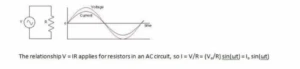
In a resistor, the current and voltage are in phase, so both reach their peaks at the same instant.
- Law used: V = IR applies to a resistor in an AC circuit.
- Current: I = V/R = (Vo/R) sin(ωt) = Io sin(ωt).
- Phase: phase describes the timing of the current relative to the voltage.
- Circuits with C or L: capacitors and inductors (coils) give very different phase relationships.
How does a capacitor behave in an AC circuit?
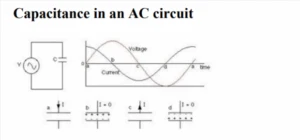
In a purely capacitive circuit, the current leads the voltage by 90°.
- Capacitor: a device for storing charge.
- Phase difference: the current reaches its peak 90° (1/4 cycle) before the voltage does.
- Charge and voltage: CV = Q.
- Current and charge: I = ∆Q/∆t.
What happens to the current during one cycle of the voltage?
The current is largest when the voltage is changing fastest and is zero when the voltage is at a peak.
- Step 1 (a to b): the voltage is zero at a and the capacitor is uncharged. The voltage rises quickly, so a large current builds up charge on the plates. Near the peak the voltage changes slowly, so less current flows. At b the capacitor is fully charged and the current is momentarily zero.
- Step 2 (b to c): the voltage falls and the capacitor discharges, so the current reverses direction. The voltage passes through zero at c very rapidly, so the current is large and negative.
- Step 3 (c to d): the voltage is negative and charge builds up with opposite polarity. The current stays negative and drops to zero as the voltage reaches its negative peak at d.
- Step 4 (d to a): the voltage heads back towards zero and the capacitor discharges. At zero the voltage has completed a full cycle and is back at a.
What is capacitive reactance?
Capacitive reactance (XC) is the opposition a capacitor offers to alternating current, measured in ohms.
- Capacitance: a larger capacitance needs more charge to reach a given voltage, so the current is higher.
- Frequency: a higher frequency leaves less time to change the voltage, so the current is larger.
- Result: current rises as capacitance and frequency rise, so XC is inversely proportional to both.
- Voltage across a capacitor: V = IXC, using r.m.s. values.
XC = 1/ωC = 1/2πfC
Worked example: a 100 µF capacitor at 50 Hz has XC = 1/(2π × 50 × 0.0001), which is about 31.8 Ω.
How does an inductor behave in an AC circuit?
In a purely inductive circuit, the current lags the voltage by 90°.

- Inductor: a coil of wire, often wrapped around a ferromagnetic core.
- Phase difference: the current reaches its peak 1/4 cycle after the voltage peaks.
- Cause: the law of induction, e = -N∆ɸ/∆t or e = -L∆I/∆t.
- Loop rule: Kirchhoff’s loop rule gives V – L∆I/∆t = 0, so V = L∆I/∆t.
- Source of voltage: in a capacitor it comes from stored charge, but in an inductor it comes from a changing current and magnetic field.
- Large positive voltage: needs a large increase in current.
- Zero voltage: the current stops changing for an instant.
- Large negative voltage: the current falls quickly.
- Result: the current varies like a negative cosine wave when the voltage follows a sine wave.
How does the current depend on frequency and inductance?
The current in an inductor falls when the frequency or the inductance increases.
- Higher frequency: there is less time for the current to change, so the current is smaller.
- Higher inductance: the coil resists changes in current more strongly, so the current is smaller.
What is inductive reactance?
Inductive reactance (XL) is the opposition an inductor offers to alternating current, measured in ohms.
XL = ωL = 2πfL
- L: the inductance of the coil, measured in henry (H).
- Depends on: the geometry of the coil and whether it has a ferromagnetic core.
- Frequency: XL increases as frequency increases.
- Voltage across an inductor: V = IXL.
Worked example: a 0.1 H inductor at 50 Hz has XL = 2π × 50 × 0.1, which is about 31.4 Ω.
Where does the energy go in an AC circuit?
A resistor turns electrical energy into heat, while a capacitor and an inductor store energy and give it back.
- Resistor: power is dissipated as heat.
- Capacitor: no energy is lost. Energy is stored in the electric field between the plates, then returned. Energy = ½CV2
- Inductor: no energy is lost. Energy is stored in the magnetic field, then returned to the circuit. Energy = ½LI2
- Energy density of an electric field: energy per unit volume, equal to ½ε0E2 when there is no dielectric.
- With a dielectric: the energy density is multiplied by the dielectric constant.
How do a resistor, a capacitor and an inductor compare in AC?
The three components differ in their opposition, phase and energy behaviour, as shown below.
| Property | Resistor | Capacitor | Inductor |
|---|---|---|---|
| Opposition | Resistance R | XC = 1/2πfC | XL = 2πfL |
| Phase of current | In phase with voltage | Leads voltage by 90° | Lags voltage by 90° |
| Effect of higher frequency | No change | Opposition falls | Opposition rises |
| Energy | Lost as heat | Stored in electric field | Stored in magnetic field |
What are reactance and impedance in AC circuits?
Reactance is the opposition of an inductor or capacitor to alternating current, and impedance is the total opposition of the whole circuit.
- Reactance (X): due to an inductor, a capacitor or both, and measured in ohms.
- Impedance (Z): due to resistance and reactance together, and measured in ohms.
What is reactance?
Reactance is the opposition offered to the flow of alternating current by an inductor or a capacitor.
- Inductor of inductance L: reactance is ωL.
- Capacitor of capacitance C: reactance is 1/ωC.
How is inductive reactance obtained from the current?
Take an inductor of L henry connected to a source V = Vm sin ωt.
- ω: the angular frequency in radian/sec, where ω = 2πf.
- f: the supply frequency in Hz.
- I: the current in the circuit.

The current is I = Vm sin(ωt – π/2) / (ωL), so its maximum value is:
Im = Vm/ωL = Vm/XL, where XL = ωL
- Comparison with Ohm’s law: I = V/R, so XL does the job of R.
- Name: it is called inductive reactance because an inductor offers it.
How is capacitive reactance obtained from the current?
Now take a capacitor connected to an alternating source.

The current is I = (VmωC) sin(ωt + π/2). It is largest when sin(ωt + π/2) = 1:
Im = Vm/(1/ωC) = Vm/XC
- Comparison with Ohm’s law: XC acts as a resistance to the current.
- Name: XC = 1/ωC is called capacitive reactance.
What is impedance?
Impedance (Z) is the net opposition to the flow of current in an AC circuit, expressed as Z = R + jX, where X is the reactance.
- R and L: opposition from resistance and inductance.
- R and C: opposition from resistance and capacitance.
- R, L and C: opposition from all three together.
How is impedance found for a resistor and inductor in series?
Take a pure resistance R in series with a pure inductive coil of inductance L.
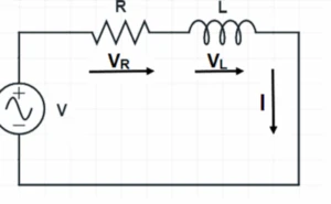
- V: r.m.s. value of the applied voltage.
- I: r.m.s. value of the circuit current.
- VR: voltage drop across R.
- VL: voltage drop across the coil.
- Take the circuit current as the reference phasor.
- Draw VR in phase with the current I.
- Draw VL leading the current I by 90°.
- Join them in the voltage triangle OAB.
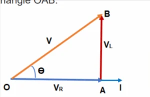
- OA: the voltage drop in resistance, VR.
- AB: the inductive voltage drop, VL.
- OB: the supply voltage V, which is the hypotenuse of the triangle.
The supply voltage is then calculated as shown below.
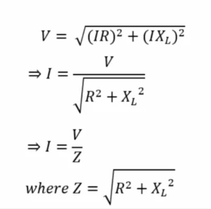
Z = √(R2 + XL2) is the magnitude of the impedance of the circuit.
The supply voltage can also be written using the j operator:
V = (IR) + j(IXL)
I = V/(R + jXL) = V/Z
- Impedance: Z = R + jX, a complex quantity.
- Phase angle: the angle Z makes with the reference phasor is found from tan θ = X/R.
Evaluation
- State the relationship between the r.m.s. value and the peak value of a sine wave.
- Describe the phase relationship between current and voltage in a purely resistive circuit, a purely capacitive circuit and a purely inductive circuit.
- Write the expressions for capacitive reactance and inductive reactance.
- Define impedance and state the expression for it in terms of R and X.
- Calculate the inductive reactance of a 0.2 H coil at a frequency of 50 Hz.
Assignment
Explain why the current in a capacitor increases as the capacitance and the frequency increase, then explain what happens to electrical energy in a resistor, a capacitor and an inductor in an AC circuit.
This term's Physics topics
SS3 Second Term · 6 topics
SS3 Physics Lesson Notes for Other Topics
Electromagnetic Field
Read the full lesson note.
Electromagnetic Induction
Read the full lesson note.

Models of an Atom
Read the full lesson note.

Nucleus & Radioactivity, Nuclear Reaction.
Read the full lesson note.
Energy Quantization
Read the full lesson note.

Introduction to Lasers
Read the full lesson note.

Fibre Optics
Read the full lesson note.

Semiconductor(Electronics) Electrical Conduction through Solid Materials
Read the full lesson note.

Electric Field, Laws of Electrostatics, Capacitor & Capacitance
Read the full lesson note.

Electrolysis: Electrical Conduction through Liquid, and Gases.
Read the full lesson note.
Electromagnetic Wave and Capacitance
Read the full lesson note.

Gravitational Field
Read the full lesson note.

Satellites, Basic Electronics & Semiconductors
Read the full lesson note.

Energy and Society
Read the full lesson note.

Magnet and Magnetic Field
Read the full lesson note.
Lesson Notes for Other Classes

SS1 Lesson Note
The complete lesson note to guide your studies.

SS2 Lesson Note
The complete lesson note to guide your studies.
