Machine Motion – JSS3 Basic Technology Lesson Note (Third Term)
Download Lesson NoteLesson note at a glance
- Subject
- Basic Technology
- Class
- JSS3
- Term
- Third Term
- Topic
- Machine Motion
- Order
- Topic 3 of 3 this term
- Reading time
- 7 min
Machine motion
Linear motion refers to the movement of an object in a straight line, where the displacement of the object is directly proportional to time. The term “linear” implies that the motion occurs along a single, straight path without any deviation. The characteristics of linear motion in engineering include:
- Direction: The object moves along a specific direction, maintaining a constant path.
- Speed: The speed of the object can be constant or vary uniformly, but the overall motion occurs linearly.
Arrangement of lever, linkages, slides, and slots to produce Linear Motion in mechanical system
In a mechanical system, the arrangement of levers, linkages, slides, and slots can be ingeniously designed to produce linear motion. Here’s an overview of how these components work together:
- Lever: Levers are rigid structures that rotate around a fixed point called a fulcrum. They are categorized into three classes based on the relative positions of the effort (applied force), load (resistance), and fulcrum.
To use a lever arrangement to bring about linear motion, first identify the lever arm and pivot point. Apply a force to the lever arm at a distance from the pivot point, causing the arm to rotate around the pivot point.
2. Linkages: Linkages are assemblies of rigid bodies (links) connected by joints. They can transfer motion and force between different parts of a mechanical system.
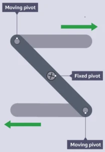
In the case of linear motion, various types of linkages, such as the slider-crank mechanism, can be employed. This mechanism involves a sliding joint that converts rotary motion into linear motion.
- Slides: Slides are components that facilitate linear movement along a fixed path. They can include linear bearings, rails, and guides that allow smooth and controlled motion. A slide can bring about linear motion by providing a smooth, inclined surface for an object to slide down. The force of gravity acting on the object causes it to move down the slide in a straight line, resulting in linear motion.
- Slots: Slots are elongated holes or openings in a structure. When used in conjunction with pins or sliders, they allow linear motion within a limited range. Slots can be part of a mechanism where the movement is guided along a straight path.
Uses of Slides in Mechanical Systems
- Linear slides, often equipped with linear bearings or guides, allow smooth and controlled linear motion. They are employed in applications like CNC machines, 3D printers, and other precision equipment to guide moving parts along a straight path.
- Adjustable slides with features like lead screws or racks and pinions enable fine-tuning of linear positions.
- Slides are often used in conjunction with other components to convert rotational motion into linear motion. For instance, a lead screw attached to a sliding mechanism can transform rotary motion into controlled linear displacement.
- Linear slides are essential in modular systems where different components need to be easily assembled and disassembled.
Uses of Slots in Mechanical Systems
- Slots can be part of mechanisms that convert rotational motion into linear motion. By guiding pins along the slots, engineers can create devices that produce linear motion as part of a larger system.
- Slots offer flexibility in adjusting the position of components within a defined range. By altering the position of pins within the slot, users can customize the linear motion parameters, providing adaptability to various requirements.
- Incorporating slots in structural components allows for modular design and the attachment of various elements.
- Slots provide a means for constrained linear motion.
EVALUATION: 1. Define linear motion.
- How can a lever be arranged to produce linear motion?
- State 3 uses of slides in mechanical system
- Mention 3 uses of slots in mechanical system
Machine motion II
The rotary motion refers to the circular movement of an object around an axis or a point. It involves rotation, where an object turns or revolves around a fixed center, typically in a circular or angular manner.
- One-Way rotary motion: A one-way rotary motion in engineering refers to rotational movement that occurs in only one direction, allowing rotation in a single, predetermined way. This type of motion is often achieved through mechanisms like clutches or ratchets, ensuring movement in a specific rotational direction. An example is the shaft of a running car
Applications
Applications of one-way rotary motion are diverse and can be found in various engineering and mechanical systems. Some notable examples include:
- Socket Wrenches and Tools: As mentioned earlier, ratchet mechanisms in tools like socket wrenches use one-way rotary motion to efficiently tighten or loosen bolts and nuts without the need to reposition the tool.
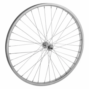
- Bicycle Freewheel: The freewheel mechanism on a bicycle’s rear wheel allows one-way rotary motion. It enables the wheel to rotate freely in one direction (forwards) while preventing backward movement when the pedals are not actively being turned.
3. Door Closers: Certain door closers use one-way rotary motion mechanisms to control the closing of doors. The mechanism allows the door to close smoothly in one direction, preventing it from swinging back open.
- Retractable Seat Belts: In automotive engineering, retractable seat belts often use one-way rotary motion mechanisms to enable smooth and controlled extension when pulled out, while retracting securely when not in use.
- Reversible Rotary Motion
Reversible rotary motion, on the other hand, allows rotation in both directions. This type of motion is commonly found in various mechanical systems where the ability to change the direction of rotation is essential. It can be achieved through mechanisms such as gears or reversible motors, providing versatility in the operation of machinery or devices. Examples of reversible rotary motion include load down of Cranes, Brakes, Clutches, and Ratchets.
Reversible rotary motion, which allows rotation in both directions, finds applications in a wide range of engineering and mechanical systems. Some examples include:
- Electric Motors: Most electric motors are designed to provide reversible rotary motion. This versatility is crucial in various applications, such as in appliances, industrial machinery, and automotive systems, where the direction of rotation may need to be changed.
- Gears and Gearboxes: Gears are fundamental in many mechanical systems, and gearboxes often provide a means for reversible rotary motion. This is vital in applications like automobiles, where the ability to move both forward and backward is essential.
- Conveyor Systems: Reversible rotary motion is employed in conveyor systems to control the movement of materials in both directions along the conveyor belt. This is common in manufacturing and logistics.
- Winches and Hoists: Devices like winches and hoists use reversible rotary motion to lift and lower loads. This capability is crucial for tasks such as material handling in construction and industrial settings.
- Wind Turbines: Some types of wind turbines use reversible rotary motion to harness wind energy and convert it into electricity. This allows the turbine to adapt to changing wind directions for optimal energy generation.
Importance of converting rotary motion to linear Linear motion
Converting rotary motion to linear motion is often necessary in engineering and various applications due to specific needs and advantages. Some of the key reasons include:
- Linear Actuation: Many mechanical systems require linear motion for specific tasks, such as moving objects along a straight path, lifting or lowering loads, or controlling linear positioning. Converting rotary motion to linear motion allows for the creation of linear actuators, devices that produce linear movement in response to rotational input.
- Precision and Control: Linear motion is often more precise and controllable in certain applications than rotary motion. Converting rotary motion to linear motion enables engineers to achieve precise movements and positioning in machinery, robotics, and other systems.
- Space Constraints: In situations where space is limited or where linear motion is more practical, converting rotary motion becomes essential. Linear motion systems can be more compact and efficient in confined spaces compared to rotational systems.
- Transmission of Forces: Linear motion is useful when the transmission of force in a straight line is required. This is common in applications like pressing, stamping, or other processes where a linear force is needed.
- Conveyor Systems: Many conveyor systems require linear motion to transport materials efficiently from one point to another. Converting rotary motion to linear motion is often used in designing conveyor belts and similar systems.
- Piston Engines: In internal combustion engines, the reciprocating motion of pistons is a result of converting the rotary motion of the crankshaft into linear motion. This linear motion is essential for driving the engine’s power cycle.

EVALUATION: 1. What is rotary motion?
- Identify and discuss the types of rotary motions you know.
- Why is it necessary to convert rotary motion to linear motion?
CLASSWORK: As in evaluation
CONCLUSION: The teacher commends the students positively
This term's Basic Technology topics
JSS3 Third Term · 3 topics
- Fault Detection
- Basic Electronics I
- Machine Motion
Third Term Basic Technology Lesson Notes for Other Topics

Health and Hygiene
Read the full lesson note.
Simple Machines
Read the full lesson note.

Booting
Read the full lesson note.

Teeth Brushing
Read the full lesson note.
Simple Machines - The Safe Use of Simple Machines
Read the full lesson note.

Care of the Nails and Hair
Read the full lesson note.

Concept of Technology
Read the full lesson note.

Steps of Booting
Read the full lesson note.

Cleanliness
Read the full lesson note.

Technology in Home - Electric Gadgets
Read the full lesson note.

First Aid
Read the full lesson note.

Technology in Transportation - Land and Air
Read the full lesson note.

First Aid (Continued)
Read the full lesson note.

What Is Water Transportation?
Read the full lesson note.

My Desktop (Review)
Read the full lesson note.
Lesson Notes for Other Classes

Basic 1 Lesson Note
The complete lesson note to guide your studies.

Basic 2 Lesson Note
The complete lesson note to guide your studies.

Basic 3 Lesson Note
The complete lesson note to guide your studies.

Basic 4 Lesson Note
The complete lesson note to guide your studies.

Basic 5 Lesson Note
The complete lesson note to guide your studies.

Basic 6 Lesson Note
The complete lesson note to guide your studies.