
Simple AC Circuit – SS3 Physics Lesson Note (Second Term)
Download this term · ₦1,000Lesson note at a glance
- Subject
- Physics
- Class
- SS3
- Term
- Second Term
- Topic
- Simple AC Circuit
- Order
- Topic 3 of 6 this term
- Reading time
- 11 min
In an alternating current (AC) circuit, the voltage oscillates in a sine wave, V = Vo sin ωt, instead of staying constant like a battery’s voltage. Resistors, capacitors and inductors oppose AC differently. Capacitors and inductors create a 90° phase difference between current and voltage, and their opposition is called reactance. Impedance is the net opposition of resistance and reactance.
Behavioural objectives
By the end of the lesson, students should be able to:
- State how the voltage in an AC circuit varies with time and relate peak and r.m.s. values.
- Describe the phase relationship between current and voltage in a resistor, a capacitor and an inductor.
- Write the expressions for capacitive reactance and inductive reactance and state how each depends on frequency.
- Explain what happens to electrical energy in a resistor, a capacitor and an inductor.
- Define reactance and impedance and write the expression Z = R + jX.
What is alternating current?
Direct current (DC) circuits involve current flowing in one direction. In alternating current (AC) circuits, instead of a constant voltage supplied by a battery, the voltage oscillates in a sine wave pattern, varying with time as V = Vo sin ωt. In a North American household circuit, the frequency is 60 Hz.
The angular frequency is related to the frequency, f, by ω = 2πf. Vo represents the maximum voltage, which in a household circuit in North America is about 170 volts. We talk of a household voltage of 120 volts, though. This number is a kind of average value of the voltage.
The particular averaging method used is called root mean square (square the voltage to make everything positive, find the average, and take the square root), or r.m.s. Voltages and currents for AC circuits are generally expressed as r.m.s. values. For a sine wave, the relationship between the peak and the r.m.s. average is:
r.m.s. value = 0.707 × peak value
How does a resistor behave in an AC circuit?
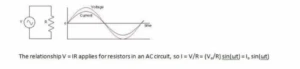
The relationship V = IR applies to resistors in an AC circuit, so:
I = V/R = (Vo/R) sin(ωt) = Io sin(ωt)
In AC circuits we often refer to the phase of the current relative to the voltage. In a circuit which only involves resistors, the current and voltage are in phase with each other, which means that the peak voltage is reached at the same instant as the peak current. In circuits which have capacitors and inductors (coils), the phase relationships are quite different.
How does a capacitor behave in an AC circuit?
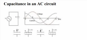
Consider a circuit which has only a capacitor and an AC power source (such as a wall outlet). A capacitor is a device for storing charge. There is a 90° phase difference between the current and voltage, with the current reaching its peak 90° (1/4 cycle) before the voltage reaches its peak. Put another way, the current leads the voltage by 90° in a purely capacitive circuit.
To understand why this is, we should review some of the relevant equations. The relationship between voltage and charge for a capacitor is CV = Q. The relationship between current and the flow of charge is I = ∆Q/∆t.
What happens to the current during one cycle of the voltage?
The AC power supply produces an oscillating voltage. We follow the circuit through one cycle of the voltage to see what happens to the current.
- Step 1: At point a (see diagram) the voltage is zero and the capacitor is uncharged. Initially, the voltage increases quickly. The voltage across the capacitor matches the power supply voltage, so the current is large enough to build up charge on the capacitor plates. The closer the voltage gets to its peak, the slower it changes, meaning less current has to flow. When the voltage reaches a peak at point b, the capacitor is fully charged and the current is momentarily zero.
- Step 2: After reaching a peak, the voltage starts dropping. The capacitor must discharge now, so the current reverses direction. When the voltage passes through zero at point c, it changes quite rapidly. To match this voltage the current must be large and negative.
- Step 3: Between points c and d, the voltage is negative. Charge builds up again on the capacitor plates, but the polarity is opposite to what it was in step 1. Again the current is negative, and as the voltage reaches its negative peak at point d the current drops to zero.
- Step 4: After point d, the voltage heads toward zero and the capacitor must discharge. When the voltage reaches zero it has gone through a full cycle, so it is back at point a to repeat the cycle.
What is capacitive reactance?
The larger the capacitance of the capacitor, the more charge has to flow to build up a particular voltage on the plates, and the higher the current will be. The higher the frequency of the voltage, the shorter the time available to change the voltage, so the larger the current has to be. The current, then, increases as the capacitance increases and as the frequency increases.
Usually, this is thought of in terms of the effective resistance of the capacitor, which is known as the capacitive reactance, measured in ohms. There is an inverse relationship between current and resistance, so the capacitive reactance is inversely proportional to the capacitance and the frequency:
XC = 1/ωC = 1/2πfC
We can use this like a resistance in an equation of the form V = IR to get the voltage across the capacitor:
V = IXC
Note that V and I are generally the r.m.s. values of the voltage and current.
How does an inductor behave in an AC circuit?

An inductor is simply a coil of wire (often wrapped around a piece of ferromagnet). In a circuit composed only of an inductor and an AC power source, there is again a 90° phase difference between the voltage and the current in the inductor. This time, however, the current lags the voltage by 90°, so it reaches its peak 1/4 cycle after the voltage peaks. The reason for this has to do with the law of induction:
e = -N∆ɸ/∆t or e = -L∆I/∆t
Applying Kirchhoff’s loop rule to the circuit above gives:
V – L∆I/∆t = 0, so V = L∆I/∆t
As the voltage from the power source increases from zero, the voltage on the inductor matches it. With the capacitor, the voltage comes from the charge stored on the capacitor plates (or, equivalently, from the electric field between the plates). With the inductor, the voltage comes from changing the flux through the coil, or, equivalently, changing the current through the coil, which changes the magnetic field in the coil.
To produce a large positive voltage, a large increase in current is required. When the voltage passes through zero, the current should stop changing just for an instant. When the voltage is large and negative, the current should be decreasing quickly. These conditions can all be satisfied by having the current vary like a negative cosine wave when the voltage follows a sine wave.
How does the current depend on frequency and inductance?
If the frequency is raised, there is less time to change the voltage. If the time interval is reduced, the change in current is also reduced, so the current is lower. The current is also reduced if the inductance is increased.
What is inductive reactance?
As with the capacitor, this is usually put in terms of the effective resistance of the inductor. This effective resistance is known as the inductive reactance, given by:
XL = ωL = 2πfL
Here L is the inductance of the coil, which depends on the geometry of the coil and whether it has a ferromagnetic core. The unit of inductance is the henry.
As with capacitive reactance, the voltage across the inductor is given by V = IXL.
Where does the energy go in an AC circuit?
One of the main differences between resistors, capacitors and inductors in AC circuits is in what happens with the electrical energy.
- Resistor: power is simply dissipated as heat.
- Capacitor: no energy is lost because the capacitor alternately stores charge and then gives it back again. Energy is stored in the electric field between the capacitor plates. The energy stored in a capacitor is: Energy = ½ CV2
- Inductor: no energy is lost because energy is alternately stored in the magnetic field and then given back to the circuit. The energy stored in an inductor is: Energy = ½ LI2
There is energy associated with an electric field. In general, the energy density (energy per unit volume) in an electric field with no dielectric is:
Energy density = ½ ε0E2
With a dielectric, the energy density is multiplied by the dielectric constant.
What are reactance and impedance in AC circuits?
Reactance is defined as an electrical quantity due to which alternating current is opposed by an inductor or capacitor or a combination of both of them in a circuit. Impedance is the net opposing factor to alternating current. Reactance may also be called impedance offered either by an inductor or capacitor. Reactance is denoted by X and impedance by Z.
What is reactance?
Reactance is the opposition offered to the flow of alternating current. This opposition may either be due to an inductor (L) or a capacitor (C). The value of reactance due to an inductor of inductance L is ωL, whereas its value for a capacitor of capacitance C is 1/ωC.
Explanation of reactance
Consider a circuit in which an inductor with inductance L henry is connected to an alternating source V = Vm sin ωt. Here, ω is the angular frequency in radian/sec, ω = 2πf, where f is the supply frequency in Hz. The current in the circuit is I.

The current I flowing through the circuit is equal to Vm sin(ωt – π/2) / (ωL). Hence, the maximum value of this current is:
Im = Vm/ωL = Vm/XL, where XL = ωL
Observe the above expression of current and compare it with Ohm’s law (I = V/R). Here XL does the job of R. That is, XL = ωL opposes the flow of current just like a resistance does. This is the reason it is called reactance. Since it is offered by an inductor, it is called inductive reactance and indicated by the symbol XL.
Now consider another circuit consisting of a capacitor and an alternating source, as shown below.

The current through the circuit is equal to (VmωC) sin(ωt + π/2). The maximum value of current takes place when sin(ωt + π/2) = 1, and this value is:
Im = Vm/(1/ωC) = Vm/XC
On comparing this value of current Im with Ohm’s law (I = V/R), it is clear that XC opposes the flow of current and acts as a resistance. This XC = 1/ωC is called capacitive reactance.
What is impedance?
Impedance in an alternating current circuit is defined as the net opposing factor to the flow of current. This opposition may be due to resistance and inductance, or resistance and capacitance, or resistance, inductance and capacitance. It is denoted by the symbol Z. Z is often expressed as Z = R + jX, where X is the reactance.
Explanation of impedance
To understand impedance clearly, consider the circuit shown below. In this circuit, a pure resistance R and a pure inductive coil with inductance L are connected in series.
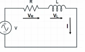
Let:
- V = r.m.s. value of applied voltage
- I = r.m.s. value of circuit current
- VR = voltage drop across R
- VL = voltage drop across the coil
Assume the circuit current to be the reference phasor. The voltage drop in the resistance is in phase with current I. The voltage drop in the inductive coil leads the current I by 90°. These voltage drops are shown in voltage triangle OAB.
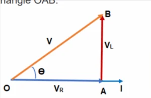
Vectors OA, AB and OB represent the voltage drop in resistance (VR), the inductive voltage drop (VL) and the supply voltage (V) respectively. The supply voltage (V) is the hypotenuse of this voltage triangle. Therefore, the supply voltage may be calculated as below.
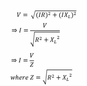
The quantity Z is the magnitude of the impedance of the alternating current circuit. From the voltage triangle, the supply voltage may also be written using the j operator. This is shown below.
V = (IR) + j(IXL)
I = V/(R + jXL) = V/Z
Thus, impedance Z = R + jX, and impedance is a complex quantity. The angle which Z makes with the reference phasor is calculated from tan θ = X/R.
Evaluation
- State the relationship between the r.m.s. value and the peak value of a sine wave.
- Describe the phase relationship between current and voltage in a purely resistive circuit, a purely capacitive circuit and a purely inductive circuit.
- Write the expressions for capacitive reactance and inductive reactance.
- Define impedance and state the expression for it in terms of R and X.
Assignment
- Explain why the current in a capacitor increases as the capacitance and the frequency increase.
- Explain what happens to electrical energy in a resistor, a capacitor and an inductor in an AC circuit.
This term's Physics topics
SS3 Second Term · 6 topics
Get Physics as PDF and Word
Every week of SS3 Physics, Second Term, formatted and ready to print. Ad-free, and the copy lock comes off.
Get this term Card, bank transfer, USSD or OPay
Second Term Physics Lesson Notes for Other Topics

Energy Quantization
Read the full lesson note.

Nucleus & Radioactivity, Nuclear Reaction.
Read the full lesson note.

Models of an Atom
Read the full lesson note.
Electromagnetic Induction
Read the full lesson note.

Electromagnetic Field
Read the full lesson note.

Heat Capacity And Specific Heat Capacity
Read the full lesson note.

Heat Energy
Read the full lesson note.

Evaporation
Read the full lesson note.

Latent Heat
Read the full lesson note.
Vapour Pressure
Read the full lesson note.
Gas Laws
Read the full lesson note.
Production And Propagation Of Waves
Read the full lesson note.

Properties Of Waves
Read the full lesson note.

Light Wave
Read the full lesson note.

Heat Energy
Read the full lesson note.
Lesson Notes for Other Classes

Basic 1 Lesson Note
The complete lesson note to guide your studies.

Basic 2 Lesson Note
The complete lesson note to guide your studies.

Basic 3 Lesson Note
The complete lesson note to guide your studies.

Basic 4 Lesson Note
The complete lesson note to guide your studies.

Basic 5 Lesson Note
The complete lesson note to guide your studies.

Basic 6 Lesson Note
The complete lesson note to guide your studies.
